Taffrail
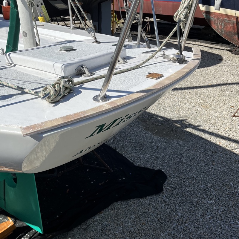
The taffrail posed a particular set of challenges. Having no experience in steam bending, I was reluctant to try to steam a straight rail to such a tight arc (more on steam bending later). Instead, I found some wider (2” x 5”) teak lumber which I planned to cut and epoxy into a rough “V” and cut the taffrail piece using a template. As with the bow section, I figured it was best to first template this using cheap 2x6” lumber from the big box store.
Template and prototype
My first step was to get the dimensions of my transom. At first I tried laying down a piece of scrap 1/4” plywood to trace the transom from underneath. This didn’t turn out to be terribly helpful. Instead, I assumed that the transom was close to a geometric arc and measured its width and height (or in geometric terms, its chord and saggita). I measured the transom at 52” wide (the chord) and 6” high (the saggita).
Back in my workshop, I made a jig from 1/4” strip to trace an arc of the correct dimensions onto 1/8” MDF. At this point I wasn’t sure how the taffrail would join with the toe rails so I actually went several inches wider than what I might need to allow some flexibility. This would define the outside edge of the taffrail.
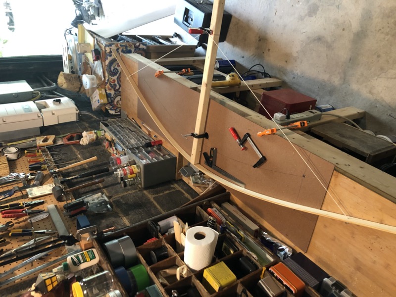
I then drew 3 radii at the ends and middle of my arc (if you’ve forgotten high school geometry, here’s how), measured in 2.5” (2” for the width of my taffrail plus 1/2” for the bevel cut), and used the jig to connect these points to outline the inside edge of the taffrail. Then I squared off the ends and cut out the template with a jigsaw. This technique produces an arc of equal thickness; if I just slid the whole jig down 2.5” the taffrail would be slightly thicker at the ends.
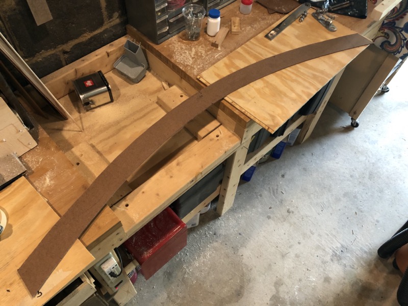
On my 2x6” I traced out as much of the template as I could fit, cut the residual off at an angle, and continued tracing the rest of the template on the second section. These two pieces glued together were sufficient to fit the entire template.
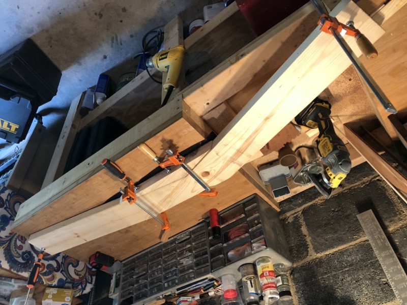
Once the glue dried, I set my jigsaw to about 14 degrees (approximately the same profile as the old taffrail), rough cut the taffrail, and cut the bevel into the foot with a handheld router.
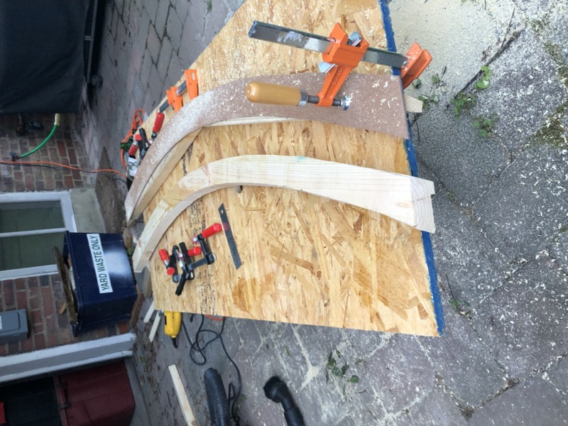
The test fit went okay, but not quite right. It turns out my arc measurements were a bit too generous, and the bevel in the foot wasn’t quite generous enough. The angle of my jigsaw also needed to be greater, at least on the outside. So I marked corrections to cut a second template and try again.
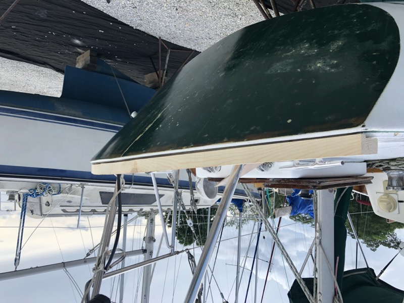
2nd Attempt: I reduced the height of the arc to 5.75” and re-cut the MDF template using the technique above, and checked the template against my transom. The center and the ends of the template lined up well, but the areas between were still a bit shy. Perhaps the transom isn’t a geometric arc after all, at least not in a practical sense.
3rd Attempt: this time I actually drew 2 “half arcs” each connecting the center point with one of the ends. This turned out to be pretty close, so I cut another prototype from scrap timber. I’ve included the exact dimensions of the 3rd pattern below in case it’s helpful.

From this template I cut a new prototype from more scrap lumber (this time using 2x4s with a lot more joints), cutting at about a 17 degree angle with the jigsaw and a bit more aggressive with the router.
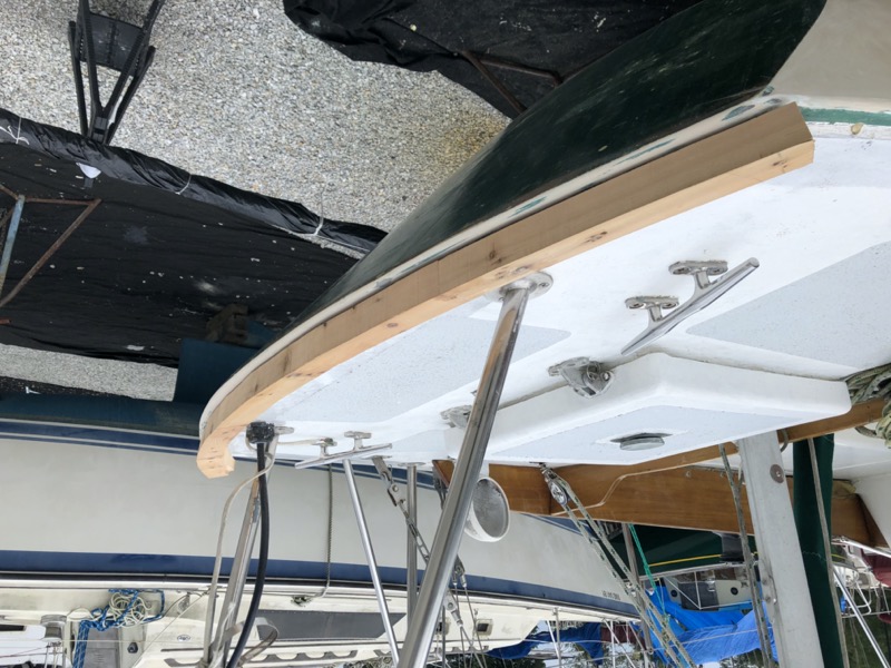
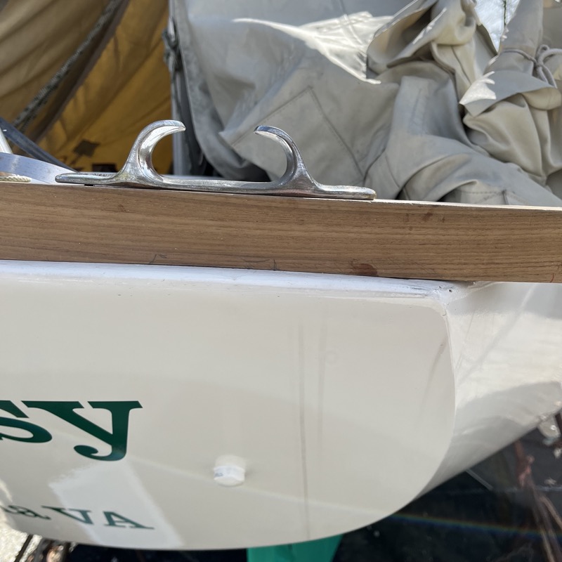
With the taffrail’s basic profile worked out, my next step was to work out how the holes for the fastener bolts would be determined. This was a tricky issue given the sharp angle of the Seabreeze transom, which leaves little room beneath deck for the bolts. I also needed to allow for a pair of stern line chocks shown in the picture below. The chocks ruled out any ideas about “fudging” the angle of the fastener bolts; they would have to be perpendicular to the top of the transom toerail section for the chock bolts to mate correctly. As shown in the picture, the chocks were previously mounted on risers, possibly to deal with these very clearance issues, but I wanted to avoid that hack if possible and mount them directly to the rails.
Before cutting the actual teak I took careful measurements of the deck, the deck-hull join, and the angle of the transom (almost exactly 45 degrees). The thickness of both the deck and the hull were also factors. To estimate the thickness of the hull I measured the distance from one of my stanchion bolts to the edge of the deck, both above and below deck, and took the difference.
Then I fed my measurements into an illustration program to produce this diagram on top of a 1/8” grid. This is exactly to scale, including the widths and lengths of the fastener bolts (deck-hull fasteners in orange, taffrail fasteners in blue). On my boat, the cable clam is the deck fitting that comes closest to the toerail so I added it for reference.
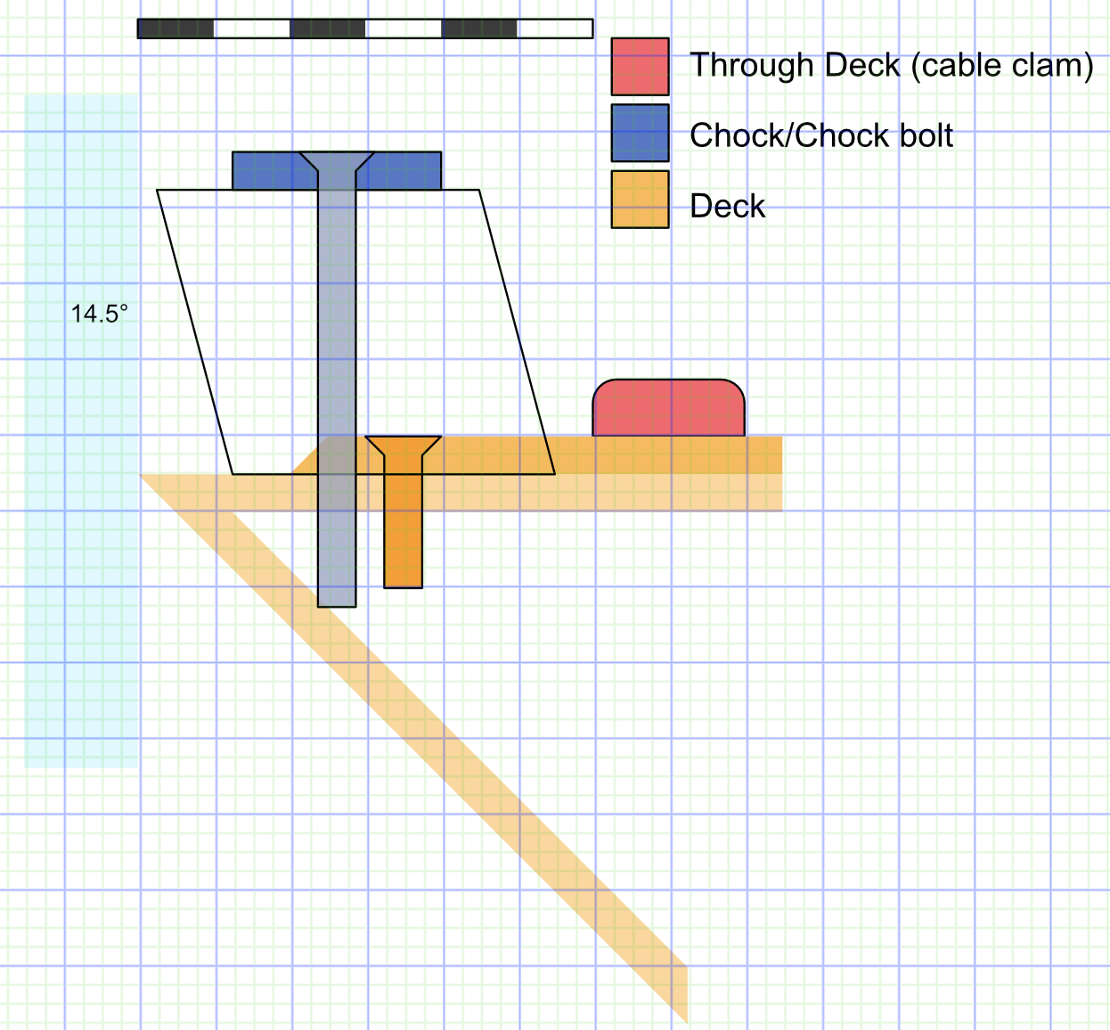
This gave me a way to play around with both the width and position of the taffrail prior to doing actual cuts on my teak timber. I decided to make the taffrail 2 1/8” wide (1/8” wider than the port and starboard sections) to so that the fastener bolts could be positioned just a bit further away from the edge of the hull but still be centered. Still, there would be very little clearance for the fastener bolts, particularly those for the chocks, and I expected I would have to cut those four bolts slightly shorter. However, since the new taffrail was slightly wider than the previous one, I could get a bit more space below deck by moving the chocks slightly inward. I also wanted to move the chocks a bit closer to the corners than previous to align with how I tie my stern lines in my home slip.
Rough cutting the taffrail
With the fastener bolts worked out (for the time being) it was time to (finally!) cut the final taffrail. I started by cutting the 2x5” timber at an angle and gluing it into the “V” I would need using epoxy thickened with teak sawdust.
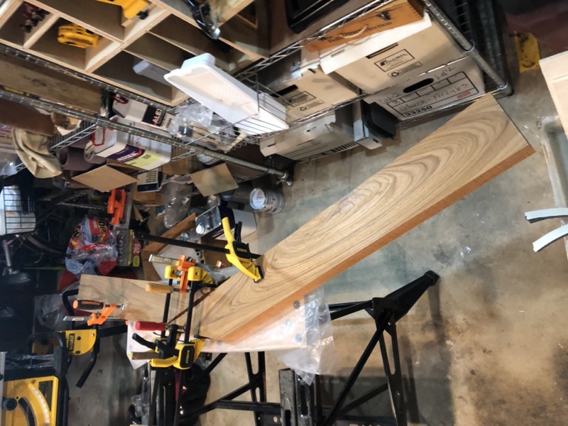
Once that cured, I simply laid the MDF template on top of the timber and traced it out:
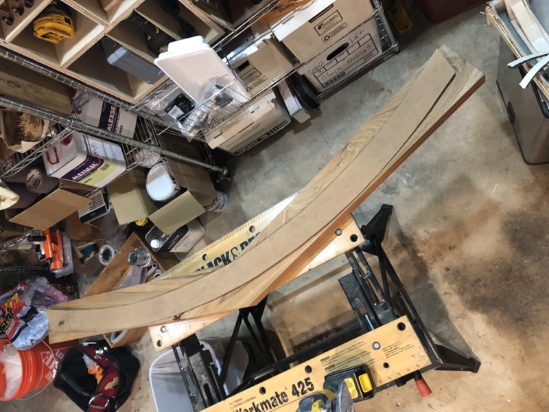
Then I cut the timber with a jigsaw set to a 14-degree angle (more or less). I also did a bit of finish sanding, including rounding off the top edges, although I didn’t take pictures of this step.
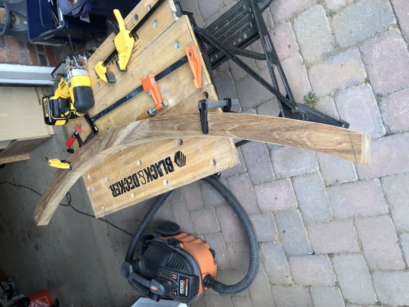
The taffrail foot would need a cutout to account for the deck-hull join shown in the illustration above, leaving about a 3/8” foot. Unfortunately, I don’t have a complete router table and had to make do with my hand-held Dewalt. I already knew from the prototype that the router could easily slip and cut the wrong way. But fortunately, Dewalt makes this handy edge guide which would prevent the router from cutting into the foot (slipping and cutting the other way would be fine). So I broke this task into two parts. First, I used the edge guide to cut a groove parallel to the curve of the taffrail that would define the foot. For this I used a 3/8” straight bit and made two passes at 1/8” and 1/4” depths.
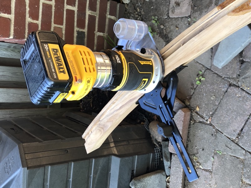
The groove gave me a safety margin to remove the remaining material without a jig. So I switched to a wider straight bit set to a 1/4” depth and made lots of small passes over the remaining wood. So long as I worked backwards, the bottom of the taffrail provided a stable surface for the router, and I marked the top of my router with a piece of masking tape to remind me where the foot was.
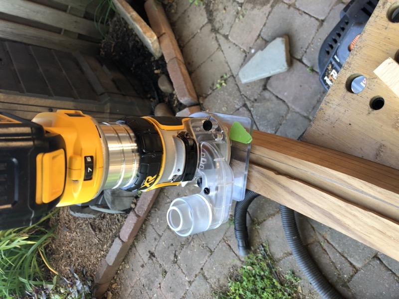
Again, working backwards in a zig-zag pattern, I removed the remaining wood in passes of about 1/4” to 3/8” each.
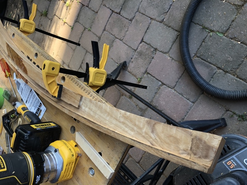
After a bit more sanding, I did a quick test fit on the boat. Here it is from behind with a jug of antifreeze to weight it in place. The approximately 1.5” gap at the corner is due to a slight curve across the deck from port to starboard: something I hadn’t anticipated. My first thought was to simply force the taffrail to conform to the deck by racheting down the fastener bolts. This would have been simpler, but Sonny talked me out of it out of concern that the short, very thick timber would ended up stressing the deck and itself if forced to bend even this much. A 1.5” bend over a longer span would be fine, and of course we would bend much more than that over the port and starboard rails.
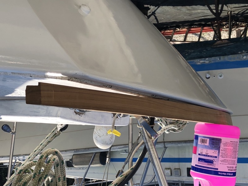
So, we would have to steam bend the taffrail after all, but vertically.
Steam bending
There is lots of information about steam bending on the internet that doesn’t need to be repeated here. I’ll just summarize by saying that I learned a ton from Louis Sauzedde at Tips from a Shipwright and followed his ingenious technique for steam bending using a plastic bag. I used the electric steam generator from Earlex which I found very easy to set up and use, and which avoided the need for a propane burner. For a plastic bag I used 6” wide nylon sterilization tubing. The tubing is inexpensive in 100’ lengths, but can be tricky to purchase if you don’t work in a dentist’s office.
But first, I needed to make a form to approximate the curve of my deck and to which I would clamp the steamed taffrail.
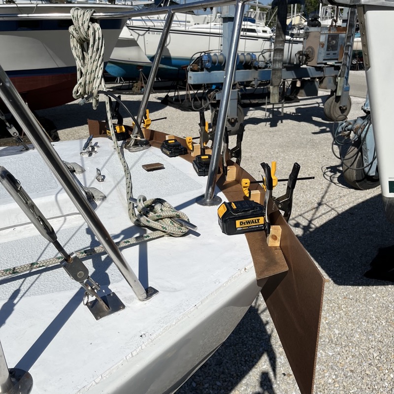
The form would have to match the transom in two dimensions. I started by laying my original 1/8” MDF template on deck, weighting it down flat, and gluing small wood blocks along the edges. To the blocks I clamped a second piece of MDF and nailed it to the blocks with a brad nailer. Then I removed the two templates as a single unit and traced the line of the first template along the second piece of MDF. That gave me a pretty decent approximation of the curve of my deck.
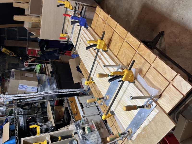
Then I used the second MDF template to cut a number of arcs from lengths of 1x2” pine which I glued to each other as well as to a separate piece of 1/2” MDF to hold the form together (it would still need reinforcement during the actual steam bending).
Once the glue dried I cut the horizontal curve out using the initial MDF template to create more access room for the clamps.
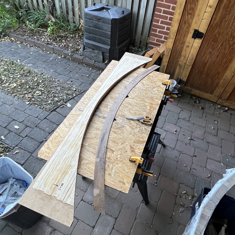
And just for good measure, I made a cast of the form using scraps of cloth, some old gelcoat and fiberglass resin, and 1/4” balsa core. I could match the cast back to the deck to confirm the form was reasonably accurate. It turned out that the form was about 10% too concave, meaning that it would result in slightly too much bend, but that’s preferable given that bet wood tends to “recall” by about that same amount.
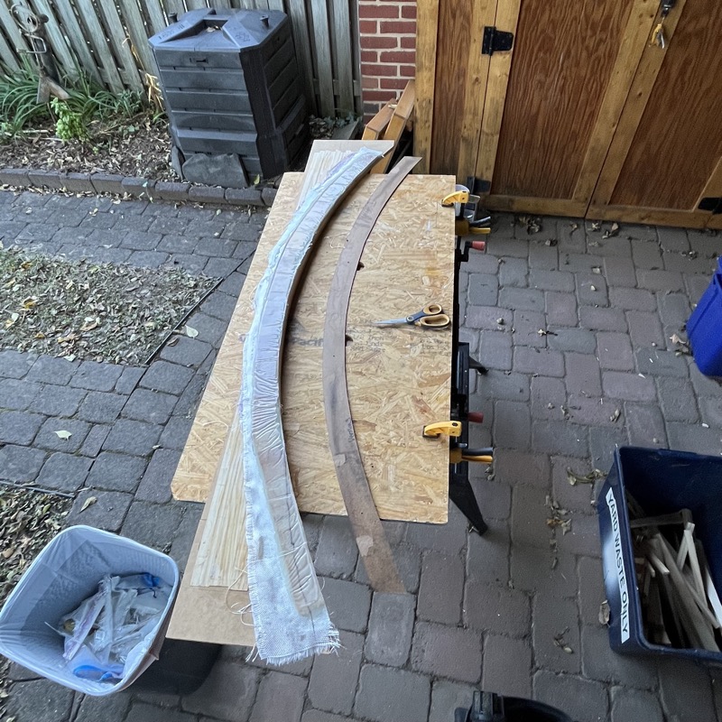
The last step was to add a 1/4” curved strip to the top of the form to match the foot I cut into the base of the taffrail. I needed this so that the taffrail could be securely clamped to the form without twisting on it. I don’t have a good picture of this, but an explanation is in the video.
Finally I was ready to steam bend! By now, it was fall of 2022, and as the weather was becoming less accommodating, we had decided to delay the installation until the following spring. I didn’t want a long time between steam bending and installation, so I put the form away until March of 2023.
Our first attempt at steam bending was a flop, and I don’t have useful photos. While the steam generator and the nylon tubing worked great, we only steamed the wood for about 90 minutes and removed the taffrail from the tubing prior to clamping. As a result, we got very little bend. I had reinforced the form with a length of cheap marble countertop from the big box store, and the marble actually cracked under the clamps’ pressure. A few days later, the taffrail “sprung” off the form when we released the clamps, and I got about 1/8” worth of bend at the very most (I was going for more like 1.5”).
The next weekend I tried again. This time I reinforced the form with a length of the original teak lumber and planned to steam the wood for at least 2-3 hours (it would actually be closer to 6). I also changed my setup so that I could clamp the taffrail to the form while it was still in the bag, as Louis suggested. This made for an otherwise long and tedious afternoon, and since I would need a couple of pairs of extra hands, I invited some friends over and we made a brunch out it, moving back and forth from the workshop to the kitchen.
To start with, I wrapped the taffrail in nylon tubing, clamped off the ends, and propped up the taffrail on spacers so that both the top and bottom of the taffrail would be exposed to steam as the bag inflated. I also cut small slits at each end of the bag to allow excess steam to escape so the bag wouldn’t explode. And I attached the steam hose to the center of the bag so that steam would distribute as evenly as possible. Then I started up the steam generator, and in about 10 minutes the bag started to inflate.
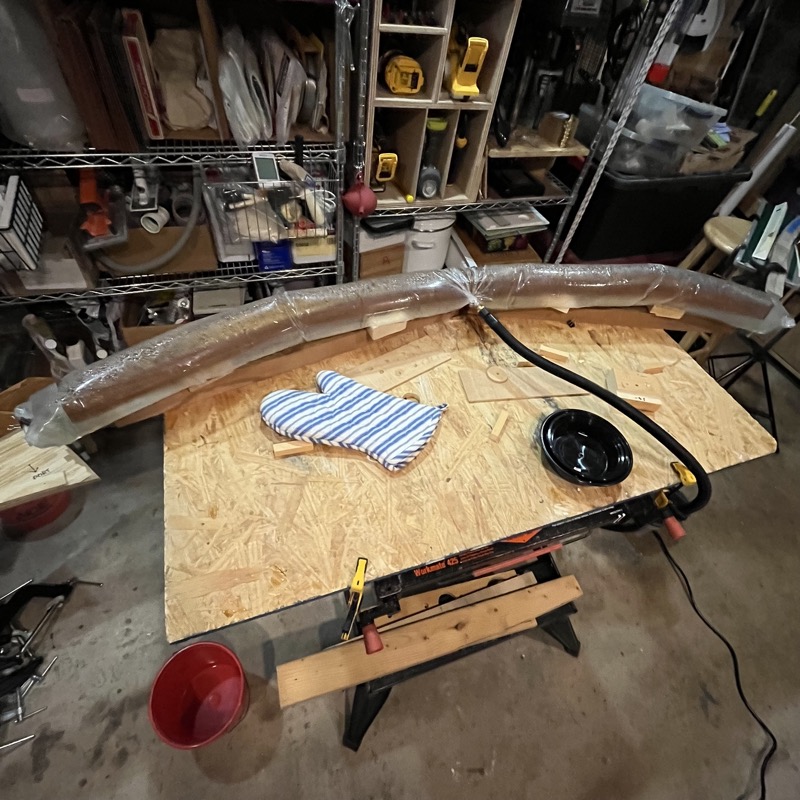
The steam was super hot of course, so I had to be careful to wear gloves or mitts whenever I had to move anything. Also, the steam generator’s manual suggested I would need to refill the water level every 90 minutes or so. I used a separate electric kettle to keep a supply of near-boiling water for refills so that the steam supply wouldn’t be interrupted for too long.
It wasn’t long before water started to pool at the bottom of the nylon bag. The spacers had a nice secondary benefit of providing room for water without immersing the taffrail. We dealt with this by periodically unclamping one end of the bag, tipping the other end of the taffrail (with potholder mitts!) to pour out the hot water into a bucket on the floor, and then quickly reclamping the the bag.
After about 3.5 hours, we moved the taffrail, still in the bag and receiving steam from the Earlex, to the form and applied clamps. We still needed to drain water from the bag periodically, which we did by tilting the entire work table.
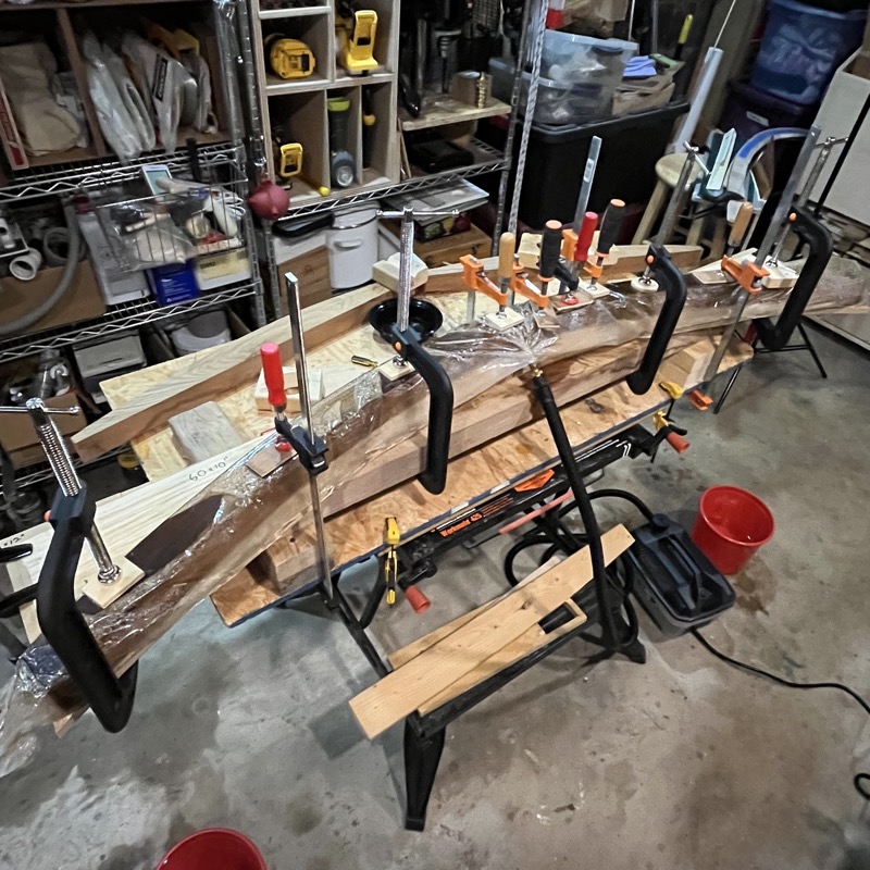
2.5 hours later, I turned off the steam generator and, once the bag had cooled a bit, cut away the top part of the bag with scissors. 6 hours of steaming might have been excessive, but at the time I thought it would be best to over-compensate from the first attempt, and anyway we were enjoying brunch cocktails upstairs. It had already become obvious though that the intense steam had weakened the scarf joint at the center to an unknown degree.
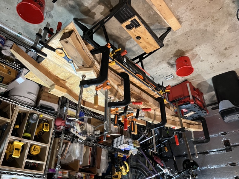
I let the taffrail sit for 2 days before releasing the clamps. The good news was that the extra steam time definitely increased the amount of bend I got, and the taffrail conformed nearly perfectly to the form with almost no “spring back” when I released the clamps. Yay!
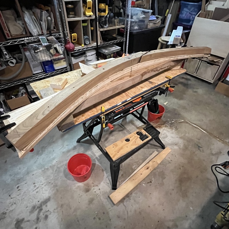
The bad news, at least initially, was that the steam had completely dissolved the epoxy scarf joint, and I now had two separate pieces of wood again!
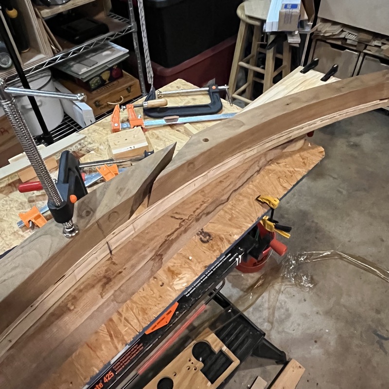
After a few moments of panic and reflection, I concluded this wasn’t necessarily a horrible development, and may actually have been a lucky break. It would be easy enough to glue the two pieces back together and use the form to ensure that the new joint matched the deck. In fact, the original scarf joint may have prevented a proper bend during the first attempt. Besides, I was noticing cracks in a few places, and more epoxy would allow me to reinforce the wood where it was starting to stress.
Here’s a video that documents the entire steam bending session:
Dry fit
Back on the boat, the initial dry fit looked quite good, but there were still a few gaps along the back that were too large to fill with bedding compound. I spent part of an afternoon with a planer and sander, adjusting the taffrail’s foot to mate with the deck as closely as possible. One spot near the (new) scarf joint was too large and had to be filled in with epoxy thickened with teak sawdust.
At the same time I drilled the holes for the fasteners. Even though I’d measured these nearly a dozen times and could see that the holes lined up well with the existing deck fasteners, I was nonetheless nervous about punching straight through the exterior side of my transom! Fortunately caution paid off and things went well. I nearly wept with joy as the fasteners slipped cleanly through the taffrail and the holes in the deck. It fit beautifully!
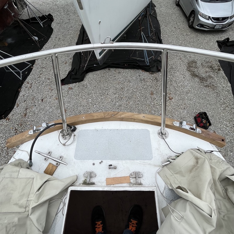
Below deck, there was ample clearance for the most part to apply a holding washer and nut to each machine bolt, so my earlier geometry paid off. I would have to “choke up” from 3” fasteners to 2.5” or 2.25” in some cases. A minor issue was that on my boat there was some rather thick and redundant fiberglass cloth jammed into the corner where my fasteners needed to go. I spent the rest of the afternoon slowly and very, very, very carefully cutting away just enough fiberglass to access the bolts. When I tightened everything down, the taffrail snugged up perfectly with no more than 3/32” of a gap.
